This topic applies to the following Generation Mode:
EHT Trigger Based PPDU
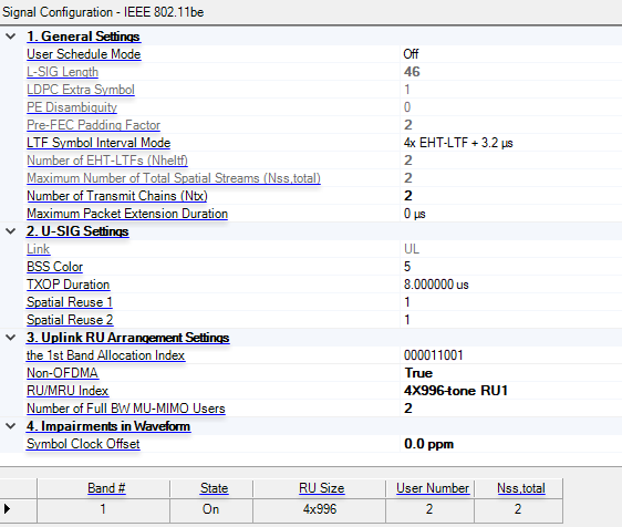
Enable/disable user schedule mode. When enabled, the parameters L-SIG Length, LDPC Extra Symbol, PE Disambiguity, and Pre-FEC Padding Factor become editable.
Sets the value of the L-SIG length field of the HE trigger-based PPDU that is the response to the trigger frame.
Indicates the presence of the extra OFDM symbol for LDPC.
Gets or sets the PE Disambiguity subfield.
Get the Pre-FEC Padding Factor.
Select the Symbol interval (with guard interval) for the EHT-LTF field. The possible options are 1x EHT-LTF + 1.6 us, 2x EHT-LTF + 1.6 us and 4x EHT-LTF + 3.2 us.
Specify the number of EHT-LTFs. If Maximum Number of Total Spatial Streams is 1, then its value is 1, otherwise its value is the ceiling of (NumOfTotalSpatialStreams / 2.0) * 2.
This is information indicating the total number of spatial streams of current Resource Unit, which is equal to the sum of the Nss for each user.
Set the number of transmit chains. When the number of instruments is more than 1 and the Channel State is Off, it automatically equals the number of instruments and cannot be changed, otherwise, it is editable.
Set or Get the Maximum Packet Extension Duration for Current PPDU. An HE PPDU may have a Packet Extension (PE) field appended at the end of the PPDU, with possible durations being 0 µs, 8 µs, or 16 µs. The PE field, when present, shall be transmitted with the same average power as the Data field, and its content is arbitrary.
Indicates whether the frame is Uplink or Downlink. The field is set to DL for TDLS and set to UL for EHT TB PPDU.
Get or Set the Base station identifier.The BSS Color field is an identifier of the BSS.
Set or Get the remaining time duration in the current TXOP. Set to 8449 μs to indicate no duration information. Set to value other than 8449 μs to indicate the duration information for NAV setting and protection of the TXOP. When the value ranges from 0 to 504 μs, the granularity is 8 μs. When the value ranges from 512 to 8448 μs, the granularity is 128 μs.
Indicates whether or not spatial reuse is allowed in a subband of the PPDU during the transmission of this PPDU, and if allowed, indicates a value that is used to determine a limit on the transmit power of a spatial reuse transmission.
If the Bandwidth field indicates 20 MHz, 40 MHz, or 80 MHz: Spatial Reuse field for the first 20-MHz subband. If the Bandwidth field indicates 160 MHz: Spatial Reuse field for first 40-MHz subband of the 160-MHz operating band. If the Bandwidth field indicates 320 MHz: each Spatial Reuse subfield is set to the smaller value of the Spatial Reuse 1 and the Spatial Reuse 2 subfield. Set to 0 (SR disallowed Entry) to disallow SRP-based spatial reuse. Set to value 1 to 14 corresponding to SRP value for SRP-based SR operation
Indicates whether or not spatial reuse is allowed in a subband of the PPDU during the transmission of this PPDU, and if allowed, indicates a value that is used to determine a limit on the transmit power of a spatial reuse transmission.
If the Bandwidth field indicates 20 MHz, 40 MHz, or 80 MHz: Spatial Reuse field for the second 20-MHz subband. When operating in 20 MHz, this field is set to same value as Spatial Reuse 1 field. When operating 40 MHz in 2.4-GHz band, this field is set to same value as Spatial Reuse 1 field. If the Bandwidth field indicates 160 MHz: Spatial Reuse field for second 40-MHz subband of the 160-MHz operating band. If the Bandwidth field indicates 320 MHz: each Spatial Reuse subfield is set to the smaller value of the Spatial Reuse 1 and the Spatial Reuse 2 subfield.
Refer to the 802.11be RU Allocation Subfield table to configure the 20-MHz band allocation index values.
Gets or sets the RU allocation index for the 1st 20-MHz subband. It may contain multiple small-size RUs/MRUs or a large-size RU/MRU that may span multiple 20-MHz subbands including the current subband.
For example, when Bandwidth is set to 80 MHz the following four band allocation index parameters appear. (See image below.) Likewise, a bandwidth of 100 MHz yields five band allocation index parameters and so on.

Choice: On | Off
Default: Off
Coupling: The Band Allocation Index is not activated when it is on, and the RU/MRU Index & Number of Full BW MU-MIMO Users are not activated when it is off.
Indicates whether OFDMA or non-OFDMA RU/MRU transmission of EHT TB PPDU is enabled for PPDU bandwidth of 160MHz or 320MHz. When enabled it indicates non-OFDMA PPDU.
For more information, see Using Non-OFDMA Mode for EHT Trigger Based PPDU.
Range: MRU1 to MRU8 for 996+484+242-tone MRU; MRU1 for 4X996-tone RU
Default: MRU1
Select the RU/MRU index for non-OFDMA EHT TB PPDU.
For more information, see Using Non-OFDMA Mode for EHT Trigger Based PPDU.
Range: 1 to 8
Default: 1
Coupling: The number of users should not be larger than Number of Transmit Chains (Ntx)
Get or Set the number of MU-MIMO users when Non-OFDMA is on.
For more information, see Using Non-OFDMA Mode for EHT Trigger Based PPDU.
Range: -300 to 300 ppm
Default: 0.0 ppm
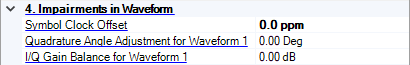
Get or set the offset to the standard symbol rate in ppm. This error is added to standard sample clock in the waveform header.
Get the index of the first 20-MHz subband where the RU/MRU is located..
Resource unit (RU) state.
Get the RU/MRU size. Please note that the instrument must have at least the equivalent bandwidth to allow the waveform to be successfully transmitted.
Get the number of users for current resource unit (RU).
This is information indicating the total number of spatial streams of current resource unit (RU), which is equal to the sum of the Nss for each user.
Range: -300 to 300 ppm
Default: 0 ppm
Get or set the offset to the standard symbol rate in ppm. This error will be added to standard sample clock in the waveform header.
Range: -90 to 90 degrees
Set the baseband quadrature angle adjustment for Waveform 1 before channel fading and mirror spectrum.
The number of parameter groups depends on Number of Transmit Chains (Ntx). Each group is identified with an incremented waveform number, such as Waveform 1, Waveform 2, and so on.
Range: -10 to 10 dB
Set the baseband IQ gain balance for Waveform 1 before channel fading and mirror spectrum.
The number of parameter groups depends on Number of Transmit Chains (Ntx). Each group is identified with an incremented waveform number, such as Waveform 1, Waveform 2, and so on.